 language
What files are needed for PCB assembly?
When preparing a printed circuit board (PCB) for assembly, one of the most critical steps is providing the manufacturer with accurate and complete documentation. Each file you submit serves a specific purpose, helping engineers and assemblers fabricate, populate, and test your circuit board correctly. Missing or incomplete files can lead to costly delays, incorrect builds, or even total assembly failure.
This article explains in detail what files are needed for PCB assembly, why each file matters, and answers some of the most frequently asked questions about PCB documentation.
Understanding PCB Assembly Documentation
PCB assembly (PCBA) is the process of soldering electronic components onto a fabricated printed circuit board to make it a functional electronic device. Before assembly begins, manufacturers require several types of files to:
- Fabricate the bare PCB board
- Identify and source the right electronic components
- Place and solder each component correctly
- Verify the board’s electrical and mechanical integrity
Without these files, even a well-designed PCB cannot be assembled correctly.
1. Gerber Files
Gerber files are the industry standard for PCB fabrication. They define every physical feature of the board, including copper traces, vias, solder masks, silkscreens, and outlines.
What Gerber files include:
- Copper Layers: Information about the top, bottom, and internal copper routing layers.
- Solder Mask Layers: Areas where solder mask should or should not be applied.
- Silkscreen Layers: Reference designators, component outlines, and markings printed on the board.
- Drill Files: Data for holes, vias, and slots used for component leads or mechanical mounting.
- Board Outline: The shape and edge dimensions of the PCB.
Typical file extensions: .gbr, .gbx, .art, .pho
Example file names:
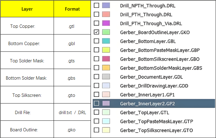
Gerber files tell the PCB manufacturer how to physically produce the board before any components are assembled. They ensure precise alignment of copper traces and layers, preventing short circuits or open connections.
2. Bill of Materials (BOM)
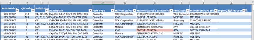
The Bill of Materials lists every electronic component that will be placed on the PCB. It is a detailed document that guides both procurement and assembly.
What a BOM includes:
- Reference Designator: Identifies the part’s location (e.g., R1, C3, U2).
- Component Value: Electrical properties such as resistance, capacitance, or IC type.
- Package Type: The physical footprint (e.g., 0805, SOT-23, QFN).
- Manufacturer Part Number (MPN): A unique code that identifies the exact component.
- Supplier Information: Distributor name or supplier part number.
- Quantity: How many of each component are required per board.
Here is an example of a BOM list:
Common file formats: .xlsx, .csv, .xls
Why it is important:
The BOM ensures that the correct parts are sourced and assembled. Missing or incorrect MPNs may cause delays, wrong substitutions, or even nonfunctional boards.
3. Pick and Place File (Centroid File)
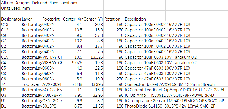
The pick-and-place file specifies where each surface-mount device (SMD) should be placed on the PCB. Automated placement machines use it to position components with precision.
What it includes:
- Reference Designator (e.g., R1, C5, U1)
- X, Y Coordinates (position on the board)
- Rotation Angle (orientation of the component)
- Side of Board (top or bottom)
Common file formats: .csv, .txt
Why it is important:
Automated assembly equipment depends on this data to accurately place components. Incorrect coordinates or missing rotation values can lead to misplaced components or orientation errors.
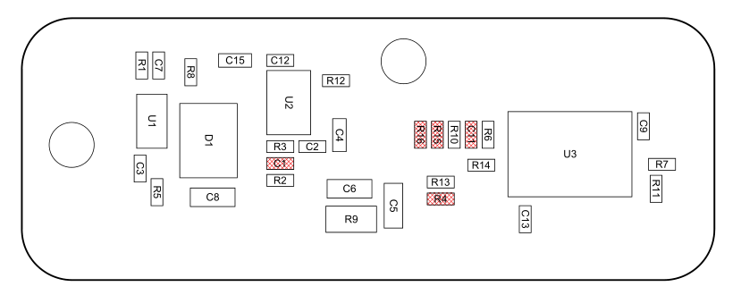
4. Assembly Drawing
An assembly drawing provides a visual reference showing how components are arranged on the PCB. It helps technicians confirm that all components are placed correctly and oriented properly.
What it includes:
- Top and bottom component outlines
- Reference designators and part labels
- Polarity marks for diodes, LEDs, and capacitors
- Pin 1 indicators for ICs
- Notes for special handling or hand-soldered components
Common file format: .pdf, .dwg
Why it is important:
The assembly drawing serves as a guide for inspection and quality control, particularly for manual or mixed (SMT and through-hole) assemblies.
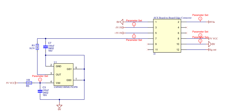
5. Schematic Diagram
The schematic shows the electrical connections between all components in the circuit. It represents the logical design rather than the physical layout.
What it includes:
- All components with their values
- Electrical connections and nets
- Power and ground references
- Test points or connectors
Common file formats: .pdf, .sch, .dsn (depending on design software)
Why it is important:
Although the schematic is not used directly in machine assembly, it is essential for electrical inspection, debugging, and verification of the final product.
6. Readme or Assembly Notes
This file contains any additional information or instructions that do not fit into other files but are necessary for successful assembly.
What it may include:
- Soldering instructions (lead-free vs. leaded)
- Moisture-sensitive component handling
- Reflow temperature profiles
- Assembly sequence or special component order
- Testing or programming procedures
Common file format: .txt, .pdf
Why it is important:
Assembly notes help avoid miscommunication and clarify special requirements that could affect the board’s functionality or quality.
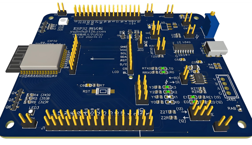
7. 3D Model Files (Optional but Recommended)
3D model files allow the assembler and mechanical engineers to visualize the assembled PCB in three dimensions. This ensures correct mechanical fit within enclosures and verifies component height or clearance issues.
Common file formats: .step, .stp, .wrl, .3DXML
Why it is important:
3D models are especially useful for projects that involve custom housings or mechanical integration, ensuring there are no conflicts between the PCB and its enclosure.
8. Optional or Advanced Files
| File Type | Description |
| Netlist File | Used to verify all electrical connections on the assembled PCB. |
| Test Procedure Files | Instructions for in-circuit or functional testing. |
| Firmware or Programming Files | Required for microcontrollers or programmable devices. |
| Panelization Drawing | Shows how multiple boards are arranged on a single panel for efficient manufacturing. |
Complete PCB Assembly File Checklist
| File Type | Description | Format |
| Gerber Files | PCB layer and fabrication data | .gbr, .gbx, .pho |
| Drill File | Hole and via data | .txt, .drl |
| Bill of Materials (BOM) | Component list and sourcing info | .csv, .xlsx |
| Pick and Place File | SMD placement coordinates | .csv, .txt |
| Assembly Drawing | Component placement guide | |
| Schematic Diagram | Circuit logic and connections | .pdf, .sch |
| Readme/Assembly Notes | Additional instructions | .txt, .pdf |
| 3D Model Files (Optional) | Mechanical verification | .step, .stp |
Frequently Asked Questions (FAQs)
1. Can I submit only my design file instead of Gerber files?
Most manufacturers require Gerber files because they are the universal standard. Some assembly houses may accept design files from software like Altium Designer, KiCad, or Eagle, but this depends on the manufacturer’s capabilities.
2. What happens if my BOM does not include manufacturer part numbers?
Without part numbers, the assembler cannot guarantee the exact components, which may cause sourcing delays or part mismatches. Always include manufacturer part numbers in the BOM.
3. Do I need both a schematic and an assembly drawing?
Yes. The schematic is used for electrical verification, while the assembly drawing ensures correct component placement and polarity during assembly.
4. In what format should I send my files to the assembler?
It is best to compress all required files into a single ZIP archive. The package should contain all Gerber files, drill files, BOM, pick-and-place file, assembly drawing, schematic, and any additional notes.
5. Can I include through-hole components in my assembly?
Yes. Be sure to identify which components are through-hole in your BOM or assembly notes so that the assembler can prepare for manual or wave soldering operations.